 |
 |
|
|
 |
 |
 |
 |
 |
presented at the Space Technology & Applications International Forum 2001
The feasibility of using solar sails to address the problem of global warming is investigated. It is shown that it is possible to reduce the earth’s solar constant with solar sails and that this approach affords a great deal of flexibility and is easily reversible. Preliminary sail specifications are developed and the magnitude of the task is analyzed.
The ability of a solar sail to generate a continuous acceleration with consuming fuel allows it to position itself between the earth and the sun and to then orbit with the same radial velocity as the earth. The very photons that provide this “free” acceleration are prevented from completing their journey and adding to the total energy transmitted from the sun to the earth. If enough photons can be intercepted, the Earth will experience a reduced solar constant and the overall global temperature would drop, even in the face of increasing levels of greenhouse gases being introduced into the earth's atmosphere.
This paper is not intended to discuss the global warming issue. It assumes that the problem is real, due either to man made or natural causes, and that lowering the average global temperature is a desirable objective. There are a large number of articles and papers that discuss the consequences of global warming but few that offer a solution, and none that offer a cheap solution, this paper included. The usual solution offered is for a worldwide reduction in the emissions of greenhouse gases. This is going to be expensive. Manne and Richels 3 (1990) suggest that the cost to reduce CO2 emissions by the United States to 80% of the 1990 level could range up to US$3.6 trillion [1012], in 1990 dollars.
If we choose to use solar sails to reduce the total quantity of sunlight hitting the planet, then how much of a reduction is necessary? The author was unable to find any good answers to this question. A 0.25% reduction in the sun’s energy output is what scientists estimate caused the Maunder minimum (Hayden, 2000). 1, 27 For reasons unknown, the sunspot cycle shut down between the mid-16th and 17th centuries. Astronomers refer to this period as the Maunder minimum. Historians refer to it as the Little Ice Age, the coldest period of time since the last great ice age, some 10,000 years ago. The Thames River in England froze for the first time in recorded history, Europe’s population growth stalled, crops failed, and sea ice cut off Iceland from Europe. Tyco Brahe, a Danish astronomer, recorded winter temperatures 2.7° Fahrenheit below average during the last two decades of the 16th century.
The ability to effectively reduce the solar constant by a similar fraction of a percent should give us enough control to adjust the global temperature to our liking. With the sheer number of unknowns swirling around the global warming issue and the complexity of the earth's climate and weather systems, this guess is perhaps as good as we can do today. One significant advantage of the solar sail approach to the problem of global warming is that it’s very flexible. Solar sails in position can quickly and easily be moved “off-line” where they won’t obstruct the sunlight hitting the earth. The deployment rate for new sails is limited only by the infrastructure for their construction and deployment.
The idea of solar sails dates back to Tsiolkovsky and Tsander in the 1920s. Most of the writings on the subject have centered on the idea of using solar sails to haul payloads around the solar system. While they may eventually prove useful at this, the basic idea can easily be adapted to reduce the quantity of sunlight hitting the earth by using solar sails as solar shields.
For a solar sail to be effective as a solar shield, it must follow a rather odd orbit. It is required to remain between the earth and sun. Yet in all other respects, its orbit will duplicate that of the earth except that the semimajor axis must be slightly smaller than the earth’s. Equation 1 is Kepler’s third law. Because the periods of the orbits for both the sail and the earth are to be exactly the same we can write equation 2. Because the semimajor axis of the sail’s orbit is smaller than the earth's, we’re required to install a fudge factor (k) in the denominator of the sail term to maintain the equality. We rearrange equation 2 into equation 3 to discover what this fudge factor is. Because we can’t adjust either the sun's mass or the gravitational constant we have to settle for reducing the sun's gravitational acceleration by furnishing a counter acceleration. This is shown in equation 4. In our case, this counter acceleration is going to be provided by the earth’s (and moon’s) gravitational pull on the sail plus the acceleration provided by light pressure on the sail. McInnes 4 developed the acceleration experienced by a solar sail in equation 5 (McInnes, 1999). We can now pull it all together into equation 6.
.
Equation 2.
.
Equation 3.
.
Equation 4.
.
Equation 5.
.
Equation 6.
There is no single solution to the problem of what semimajor axis to give to the solar sail’s orbit. There are many possibilities. The author used equations 3, 4, and 6 along with basic orbital mechanics 5 and the specific characteristics of the earth’s orbit 2 to construct a model. The moon causes some problems because it imposes tangential accelerations on the sail that must be countered by the sail. The radial component of the moon’s acceleration also varies in magnitude as the sail-moon distance changes over time. This requires the solar sail to adjust the magnitude of its acceleration. Selecting a semimajor axis 1,600,000 kilometers smaller that that of the earth, and a sail efficiency of 0.9 and using this as input into the model yields figure 1. Week 0 is perihelion. When the earth is between the sail and the moon, the sail’s mass per unit area is at its minimum (In this case 240 grams/meter ²). But as Figure 1 shows, the sail must increase its mass per unit area as the sail-moon distance decreases.
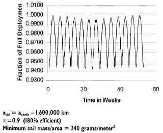
Not only must it expand and contract, the sail must also tilt back and forth to counter the tangential component of the moon's acceleration. This turns out to be a fraction of a degree, but it is there and the sail must actively sense its position and velocity, the position of the earth, moon, and sun, and adjust its position accordingly.
To determine the average annual reduction in the earth's solar constant, the sail expansion ratio, the angle of attack, and the distance from the sun must be integrated over time. The model described above does this. It assumes that the solar disk as seen from earth is uniform in its radiation output. Some solutions are listed in Tables 1-3. [Compared to the usual proposals for light sails as propulsion,] solar shields would be very heavy.
| Parameter: | Separation, D-r, along Sun-Earth axis | Contraction ratio | Sail mass density | Shading effect with 100,000 km² of sail | Total mass of sail req’d for 0.25% reduction |
|---|---|---|---|---|---|
| Units: | [km] | - | [g/m²] | [%] | [megatonnes] |
| Case 1-1 | 3,000,000 | 0.997 | 16.6 | 0.0117 | 35.0 |
| Case 1-2 | 2,750,000 | 0.997 | 18.8 | 0.0139 | 33.0 |
| Case 1-3 | 2,500,000 | 0.997 | 22.1 | 0.0171 | 32.0 |
| Case 1-4 | 2,200,000 | 0.995 | 28.7 | 0.0223 | 32.0 |
| Case 1-5 | 2,000,000 | 0.992 | 37.2 | 0.0272 | 34.0 |
| Case 1-6 | 1,800,000 | 0.984 | 56.2 | 0.0343 | 41.0 |
| Case 1-7 | 1,600,000 | 0.942 | 146.7 | 0.0444 | 82.0 |
| Case 1-8 | 1,550,000 | 0.88 | 272.2 | 0.0471 | 145.0 |
| Parameter: | Separation, D-r, along Sun-Earth axis | Contraction ratio | Sail mass density | Shading effect with 100,000 km² of sail | Total mass of sail req’d for 0.25% reduction |
|---|---|---|---|---|---|
| Units: | [km] | - | [g/m²] | [%] | [megatonnes] |
| Case 2-1 | 3,000,000 | 0.998 | 21.1 | 0.0117 | 45.0 |
| Case 2-2 | 2,750,000 | 0.997 | 23.9 | 0.0139 | 43.0 |
| Case 2-3 | 2,500,000 | 0.996 | 28.1 | 0.0171 | 41.0 |
| Case 2-4 | 2,200,000 | 0.995 | 36.5 | 0.0223 | 41.0 |
| Case 2-5 | 2,000,000 | 0.991 | 47.3 | 0.0272 | 43.0 |
| Case 2-6 | 1,800,000 | 0.984 | 71.6 | 0.0343 | 52.0 |
| Case 2-7 | 1,600,000 | 0.942 | 186.7 | 0.0444 | 105.0 |
| Case 2-8 | 1,550,000 | 0.88 | 346.4 | 0.047 | 184.0 |
| Parameter: | Separation, D-r, along Sun-Earth axis | Contraction ratio | Sail mass density | Shading effect with 100,000 km² of sail | Total mass of sail req’d for 0.25% reduction |
|---|---|---|---|---|---|
| Units: | [km] | - | [g/m²] | [%] | [megatonnes] |
| Case 3-1 | 3,000,000 | 0.998 | 27.1 | 0.011 | 50.0 |
| Case 3-2 | 2,750,000 | 0.997 | 30.8 | 0.014 | 54.9 |
| Case 3-3 | 2,500,000 | 0.996 | 36.1 | 0.017 | 53.0 |
| Case 3-4 | 2,200,000 | 0.995 | 47 | 0.022 | 52.0 |
| Case 3-5 | 2,000,000 | 0.992 | 60.8 | 0.027 | 55.8 |
| Case 3-6 | 1,800,000 | 0.983 | 92 | 0.034 | 67.0 |
| Case 3-7 | 1,600,000 | 0.942 | 240 | 0.044 | 135.2 |
| Case 3-8 | 1,550,000 | 0.88 | 445 | 0.047 | 237.1 |
The numbers from Tables 1-3 are daunting. However, there are several possibilities for reducing the number of sails needed to achieve a given result: Solar Limb Darkening (described below), and a better design for a solar sail using materials of different efficiencies. The solar sail in the above analysis consisted of a single flat surface of uniform efficiency. A more complex design might prove to be more effective at shielding the earth than the above analysis indicates.
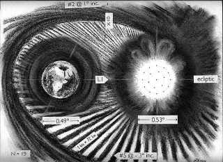
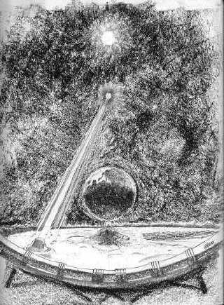
In the above analyses, the disk of the sun, as seen from earth has been considered as being of uniform brightness. This is not the case. The center of the solar disk, as seen from earth, produces more radiation that the outer limb. This is known as solar limb darkening. This is due to the specific intensity of the solar radiation field having a directional dependence. The outer limb is 40% darker than the center. By blocking the center from the sun from the earth, we will achieve a greater reduction that the above analysis indicates, perhaps by as much as 20%. This aspect of the problem requires additional study. [Ed note: One such concept is shown below.]
Each square kilometer at earth orbit receives some 1400 megawatts of energy. With a sail efficiency of 0.7, 60% of the solar radiation is not reflected and is available to be captured as useful energy. If even 10% of this non-reflected energy is converted into energy, and then beamed to the earth or the moon, some 84 megawatts of energy from each square kilometer of sail can be made available. In this way, our solar sails could become both a source of energy for human activity and a shield to lower global temperatures. Because these solar shields could weigh up to a kilogram per square meter, the extra weight could be devoted to power generation and transmission equipment. This possibility deserves additional consideration.
The effect on earth's climate and weather systems when modifying the solar constant requires considerable more study. Although this paper has treated the earth as a single unit, it is not. The solar constant reduction will not be uniform across all portions of the earth's surface nor is it uniform over time. This effect must be studied in great detail and may open the way for a certain degree of weather control. When a particular longitude moves into high noon, the solar sails could fold up and allow the full sun to get through. Later this would have to be made up by fully opening the sail thus reducing the solar flux for the next longitude. By carefully positioning the solar sails at very specific points, certain latitudes could be cooled more than others. Thus, select points on the earth's surface could be cooled more than others. This invites additional consideration and research.
Production of the quantity of sails required in Table 1, even if reduced by some fraction, is going to be a major enterprise. Reduction of the solar constant requires only a given area of sail. It does not require that it be one sail or many solar sails. The sail designers are free to size the individual sail(s) to meet production and transportation constraints.
While the sails could be made on earth and launched into space, a more efficient solution is probably going to involve the use of lunar materials. Large solar sails constructed on the moon, or in lunar orbit, can be launched fully deployed, without the need to fold up the sail. It will take decades to construct the infrastructure and more decades to produce the required number of sails. After that, sails that wear out will have to be replaced.
Solar sails can be used to adjust the earth's solar constant (in effect making it a variable that can be controlled). These sails will need to actively track their environment and be intelligent enough to act accordingly. They could be part of the solution, or even the entire solution, to the problem of global warming and climate change. Having solar sails reduce the sunlight hitting the earth could lead to some degree of weather control. The implementation of the solar sail solution requires the development of a large space infrastructure that does not exist today. As a minimum it will require a large-scale, cheap, and dependable low earth orbit access capability. It will probably require lunar mining and materials processing facilities as well as automated manufacturing and lunar launch capabilities.
We must come to a far better understanding of the sun, the earth's climate, and how these interact. If the problem of global warming is real, and if the solution involves the use of solar sails, then the infrastructure necessary to build, launch, and control these solar sails will give the people of the earth, not only a better climate, but also access to the solar system.
The author would like to thank Robert Kennedy, PE of the Ultimax Group Inc. of Oak Ridge, Tennessee, for invaluable assistance and support during the preparation of this paper. The author would also like to thank the reviewers, who provided valuable suggestions for improving this paper. All mistakes are the responsibility of the author.
ae = acceleration along earth-sun line required to maintain position relative to the earth [km/sec² ]
asail = area of the solar sail [m²]
Aearth = semimajor axis of earth’s orbit [km]
Asail = semimajor axis of solar sail’s orbit [km]
c = speed of light [km/sec]
d = distance from the sun to the moon [km]
D = distance from the sun to the earth [km]
G = gravitational constant [km³/(kg-sec²)]
k = dimensionless "adjustment" factor
Lsun = sun's luminosity [watts]
m = mass of sail [grams]
Mearth = mass of the earth [kg]
Msun = mass of the sun [kg]
eta = solar sail efficiency as defined by (McInnes, 1999)
r = distance from the sun to the sail [km]
T = time period for the earth to complete one complete orbit [seconds]
1. Hayden, Thomas, “Curtain Call” in Astronomy Magazine, edited by Bonnie Bilyeu Gordon, January 2000, pp. 45-49.
2. Krause, Helmut G. L., “Astronomical Constants of the Solar System” in Mark's Standard Handbook for Mechanical Engineers, Eighth Edition, edited by Theodore Baumeister, McGraw-Hill Book Company, New York, 1978, pp. 11:104-107.
3. Manne, Alan S. and Richels, Richard G., “CO2 Emission Limits: An Economic Cost Analysis for the USA” in The Energy Journal, edited by Leonard Waverman, Washington, D.C., 11(2), April 1990, pp. 51-74.
4. McInnes, Colin R., Solar Sailing: Technology, Dynamics and Mission Applications, Praxis Publishing, Chichester, UK, 1999.
5. Stark, John P.W., “Celestial Mechanics” in Spacecraft Systems Engineering, edited by Peter Fortescue and John Stark, John Wiley and Sons, Chichester, 1991, pp. 59-81.
6. various, Statistical Abstract of the United States: 1994 edition, (US Dept. of Commerce, Bureau of the Census, USGPO: 1994)
15Feb2001; post original as presented to STAIF 2001
15Feb2001; covered on ABC Evening News
20Feb2001; replace Table 1 with Tables 1-3.
23Feb2001; upload figures and equations.
25April2001; presentation of "AntiVenuforming Terra" at 27th Asilomar Microcomputer Workshop.
24May2001; update figures in Tables 1-3 to reflect limb darkening, L1 stationing.
07Jul2001: "Mirrors & Smoke" appears in Whole Earth Review.
24Sep2001: Finish computer graphic animation of "Mirrors & Smoke" for Belgian national television RTBF - Mati�ére Grise (in English, ’Grey Matter“. Low-rezz version of CG video archived here.
02Nov2001: Deliver invited physics seminar "Mirrors & Smoke: Changing the Solar Constant to a Solar Variable" at California Polytechnic State University, Pomona.
14Nov2001: Deliver invited engineering seminar "Mirrors & Smoke, and Other Shady Schemes" at Stanford University Computer Systems Laboratory Colloquium (EE380).
21Nov2001: Deliver luncheon lecture with updated economic forecasts to Friends of Oak Ridge National Laboratory.
30Jan2007: Advise ABC News Good Morning America re technical background and graphic to illustrate mirrors-in-space concept: 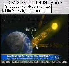 © American Broadcasting Company. Note: Not to scale.
TBD; add economic and risk analysis of reducing solar gain with sunshades vs. raising planetary orbit via multiple slingshots with KBOs (cost in energy for the two projects vs the incremental solar reduction generated by each).
Back to Directory of White Papers

For product or dealer inquiries within the USA & Canada, call:
West Coast: (888) ULTIMAX..................................................................East Coast: (800) ULTIMAX
Outside USA: +1 (865) 405-5806 -- note number has changed
or write to us:
The Ultimax Group, Inc.
112 Mason Lane
Oak Ridge, Tennessee, USA 37830-8631
or send email to robot#ultimax_com
The entire content (images and text) of these pages is copyrighted and may not be distributed, downloaded, modified, reused, re-posted or otherwise used without the express written permission of the authors.
Privacy Policy: The Ultimax Group Inc., will never sell our customer list or distribute our customer's personal data to others without permission.
Network Abuse Policy: All incidents of suspected spam, sporging, Joe jobs, etc, derived from the misuse of the data on these pages will be investigated, reported, and prosecuted to the fullest extent of the law.
These pages last updated 28 November, 2011
In all written email addresses on these pages, a hash-mark (#) has been substituted for the at-sign (@), and an underscore (_) for the period (.) in order to defeat spammers' spiders.